Selasa, 13 November 2018

Sensor


OLEH:
Rahadian Rais
1510952004


Dosen Pengampu:
Darwison,M.T


Referensi:


a. J.G. Webster (Ed), Measurement, Instrumentation, and 
Sensors Handbook CRCnetBase 1999, CRC Press LLC, 1999.
b. Sensor (sesuai buku yang digunakan sebagai presentasi) 

Rangkaian dan Simulasi

Sensor encoder ini menggunakan sensor optocoupler yang tersusun sejajar sebanyak empat buah untuk dapat membaca data yang dihasilkan dari piringan absolute encoder ketika bergerak. Sensor optocoupler yang digunakan terhubung dengan rangkaian driver untuk memperkuat keluaran (output) sinyal data yang dihasilkan sebelum dikirim ke mikrokontroler Renesas R8C/13. Kaki pin keluaran dari driver sensor encoder yang terhubung dengan port mikrokontroler Renesas R8C/13 yaitu Bit 1 (P0.4), Bit 2 (P0.5), Bit 3 (P0.6) dan Bit 4(P0.7). Skema rangkaian, konfigurasi kaki pin dan bentuk rangkaian dari driver sensor encoder 

2. Rangkaian Simulasi [kembali]


File simulasi rangkaian   =>>DOWNLOAD

Incremental Encoder

  Connection  
Description
w_in, w_out (the shaft)
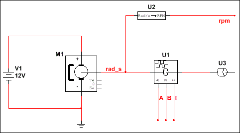
The connection to the signal that carries angular speed in rad/s as a voltage. Symbolizing a mechanical shaft, these two pins are internally short circuited; it does not matter which of the pins is connected to the speed signal. The secondary pin is available so that other mechanical components, external loads, sensors, or motion controllers can be chained and applied to the shaft, while maintaining the look of a rotary mechanical system.
A
Output pulse train of the lagging signal (lags B by a quarter cycle).
B
Output pulse train of the leading signal (leads A by a quarter cycle).
I
The index signal. A pulse is generated on this pin when the angular position is an integer multiple of 2p.
The Value tab in this component’s properties dialog box contains the following:
  Parameter  
Description
Pulses per revolution
The number of pulses per one revolution of the shaft.
Pulse amplitude
The voltage amplitude of the generated pulse on pins A,B, and I.
Initial angle
The initial angular position in rads.
Example
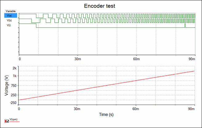
The following example illustrates the start-up of a DC machine and the corresponding encoder signals.
A 90ms transient simulation yields the following result:

This component should only be used in transient-type simulations where Initial conditions are set to User-defined.
 File simulasi rangkaian   =>>DOWNLOAD